- Work Light: clamp style lamp
- Screwdrivers: small and medium size, phillips and flat head
- Nut Drivers: 1/4", 5/16", and 11/32"
- Wrenches: 3/8", 9/16", 5/8" required, other sizes suggested
- Allen Wrenches: get an assortment of American sizes
- Needle Nose Pliers
- Hemostat. Handy for holding parts and springs. Best to have both the curved and straight versions if possible.
- Right Angled Screwdriver: both phillips and flat head.
- Alligator clips and wire. You can buy these at Radio Shack, part number 278-001, $3.69.
- Soldering Iron.
- Rosin Core 60/40 Solder.
- De-soldering tool.
- Digital Multi-Meter (DMM).
- Logic probe.
- Novus #2 or MillWax (for cleaning playfields and rubber)
- Novus #3 (for polishing metal parts)
- Johnson's Paste Wax or Meguire's Carnauba Wax (for waxing playfields and cleaning rubber)
- #47 light bulbs: have 20 or so around. Fifty is plenty to do most games. I suggest using #47 bulbs instead of #44 bulbs, as they consume less power and produce less heat.
- #555 light bulbs: have 20 or so around. Fifty is plenty to do most games.
- #906 or 912 flash bulbs: have 10 or so around.
- #89 flash bulbs: have 10 or so around.
- #1251 flash bulbs: (used on some system 11 games).
- Fuses: I would have five of any needed value on hand at all
times.
Get 250 volt fuses, not 32 volt. Radio Shack sells fuses for a decent price. Slow-blo fuses are known as MDL fuses. Fast-blo fuses are known as AGC fuses. At minimum you'll need:- 1/10 amp slo-blo (not all games use this)
- 1/4 amp slo-blo
- 1/2 amp slo-blo
- 2 amp slo-blo
- 4 amp slo-blo
- 5 amp slo-blo
- 7 amp slo-blo
- 8 amp slo-blo
- Nylon Coil Sleeves: the longer 2 3/16" length (part number 03-7066-5) are used when rebuilding flippers. The 1.75" length (part number 03-7066) are used for pop bumpers, etc. Sleeves with a lip (part number 03-7067-5) and tubing on each side (known as an "inline" sleeve) are used on the knocker, ball popper, etc. Also 03-7067-7 sleeves are used on drop target reset coils.
- Ball shooter sleeve, part number 03-7357.
- Flipper assembly, part number A-15848.
- Flipper Plunger/Link: used when rebuilding flippers (part number A-15847 or A-10656).
- Flipper Link Spacer Bushings: these small bushings go inside the flipper links (part number 02-4676).
- Flipper Coil Stops: used when rebuilding flippers (part number A-12390).
- Flipper EOS Switch: part number 03-7811.
- Flipper Cone Return spring: part number 10-376. I prefer not to use this style of return spring (I update all the system 11 games I work on to the newer WPC fliptronics style of return spring).
- 1/4" Heat Shrink Tubing: this is used on the flipper pawl when rebuilding flippers.
- Shooter Spring: the short chrome spring on the outside of the shooter mechanism (part number 10-149). These rust and look like crap in short order.
- 1 1/16" Pinballs: a new pinball will make your playfield last longer.
- Leg Levelers: replace those old crummy looking leg levelers with brand new ones. 3" are used on solid state games.
- Rubber Rings: you can order game-specific ring kits with exactly the rings you need. Don't forget to get flipper rubbers and a shooter tip.
- Transistors: keep a few TIP102, TIP42 and TIP36c transistors around.
- Diodes: keep a few 1N4004 and 1N4148 diodes around.
- Capacitors: keep a couple 2.2 mfd 250 volt non-polarized (Williams part number 5045-12098-00) around. These are used on the EOS switches.
- Bridge Rectifiers: keep an extra 35 amp, 200 volt (or higher) bridge rectifiers around, with wire leads. The industry part number is MB352 (Williams part number 5100-09690). System 11 games also use the "lug" lead version of this bridge too (Williams part number 5100-09418).
- 18,000 mfd 20 volt cap. Used for the +5 volt filter cap.
- 39k Ohm 1 or 2 watt "flameproof" resistors: often go bad on system 11 power supplies.
- 5 ohm 10 watt resistors: these flasher resistors often break.
- 330 ohms 7 watt resistors: if your game is Fire! or before, have some of these around as they often break from the under the playfield flash boards.
- 6808 CPU chip: have a couple around (they are hard to find). Replaces the hard to find 6802 used on early system 11 CPU boards.
- 6821 PIA chip: have several around as the CPU board uses 6 of these PIA chips.
- 74LS244 chip: a common TTL (transistor to transistor logic) chip used on the CPU board.
- 7408 chip: a common TTL (transistor to transistor logic) chip used on the CPU board.
- 2k by 8 CMOS static 24 pin RAM chip. The part number will be 2016 or 6116 or NTE2128. This RAM chip holds settings and bookkeeping totals.
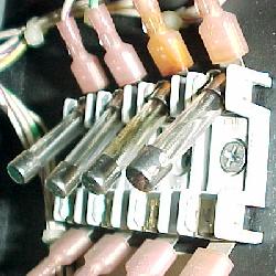
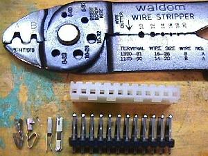
- .156" Connector pins and housings: used to repair burnt connectors.
- System 11: first generation of system 11.
- System 11A: second generation of system 11. System 11a boards can be used in system 11 games too.
- System 11B: third generation of system 11. Actually there were two version of System 11B boards, with the first version having the sound amplifier at U1 (a TDA2002). Special solenoids now CPU controlled and games have Auxiliary power driver board (actually these both started with "Big Guns, the last system 11a game).
- System 11C: fourth generation of system 11. System 11c boards can only be used in system 11c games because all sound circuits have been removed from the CPU board. There are no ROMs at U21 and U22, and most of the circuitry from the top left corner of the board has been moved to the sound board.
- High Speed, 1/86, #541
Does not use multiplexing, five score displays. - Alley Cats, 2/86
This is a Bowler, not a pinball game, but uses system11 boards. - Grand Lizard, 3/86, #523
Does not use multiplexing. - Road Kings, 7/86, #542.
First game to use a Yamaha YM2151 sound chip on the sound board. - Pinbot, 10/86, #549
- Millionaire, 1/87, #555
- F-14 Tomcat, 3/87, #554.
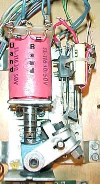
First game with four 7 character score displays. Also first game with the new FL11630 parallel wound flipper coil, which used two flipper diodes (instead of one). - Fire!, 8/87, #556
- Big Guns *, 10/87, #557.
First game to have Auxiliary power driver board and Special solenoids CPU controlled. - Big Guns *, 10/87, #557.
First game to have Auxiliary power driver board and Special solenoids CPU controlled. - Space Station, 1/88, #552
- Cyclone, 2/88, #564
- Banzai Run, 7/88, #566.
First game with an interconnect board, but the interconnect board used on this game is unique. - Swords of Fury, 8/88, #559
- Taxi, 10/88, #553.
First game with only two alpha-numeric 16 character displays, new power supply D-12246. - Jokerz, 1/89, #567.
This game only used a special stereo sound board with different sound board power requirements and cabling. - Earthshaker, 4/89, #568
- Black Knight 2000, 6/89, #563
- Police Force, 9/89, #573
- Transporter the Rescue (Bally), 6/89, #2630
- Elvira and the Party Monsters (Bally), 9/89, #782
- Bad Cats, 12/89, #575
- Mousin' Around (Bally), 12/89, #1635
- Whirlwind, 4/90, #574
- Game Show (Bally), 4/90, #985
- Roller Games, 5/90, #576
- Pool Sharks (Bally), 6/90, #1848
- Diner, 8/90, #571
- Radical (Bally), 9/90, #1904
- Riverboat Gambler, 10/90, #1966
- Bugs Bunny Birthday Ball (Bally), 11/90, #396
- Dr.Dude (Bally) *, 11/90, #737
About 100 Dr.Dude games were made with the new WPC system boards. - 1 = CPU board.
- 2 = Interconnect board (Banzai Run and later).
- 3 = Power Supply board.
- 4 = Master Score Display board.
- 5 = Auxiliary power driver board (Big Guns and later), or Slave display board on early games.
- 6 = Backbox wiring
- 7 = Cabinet wiring
- 8 = Playfield wiring
- 9 = Insert board.
- 10 = Sound board.
- 11 = Audio board.
- 15 = Flipper power supply board (Fire! and before).
1a. Getting Started: Experience, Schematics
- What Repair Experience Is Expected?
Little experience in fixing pinballs is assumed. Basic electrical knowledge is helpful, but not necessary. I do assume you can solder and use the basic features of a Digital Multi-Meter (DMM) such as measuring voltage and resistance. Please see http://marvin3m.com/begin for details on the basic electronics skills and tools you will need. This document should help if you just bought your first (or second, or third) pinball "as-is", and hope to fix it.
Got Schematics?
Having a schematic for your game would be
ideal, but sometimes you can fix your game without it. If you don't
have a schematic, order one from Steve Young's Pinball Resource
(845-473-7114 or mailto:PBResource@idsi.net?subject=from_the_Sys11_Repair_Document),
or in Europe from Pinball Heaven at mailto:Phil@pinballheaven.co.uk?subject=from_the_Sys11_repair_document.
Online schematics are available too at http://www.stormaster.com/RGP-Stuff/manuals/williams-system-11a.zip (900k) in ZIP format (WinZip required). These are system 11A schematics, from the game F-14 Tomcat. Individual scans are in TIF format.
1b. Getting Started: Necessary Tools
- Fixing electronic pinball games will require a few tools. Luckily,
most are not that specialized and are easy to get.
Non-Specialized Tools Required:
Specialized Tools Required:
These specialized electronics
tools are needed. Please see http://marvin3m.com/begin for
details on the basic electronics tools you will need.
Cleaning "Tools" Required:
1c. Getting Started: Parts to Have On-Hand
- When fixing electronic pinballs, I would highly recommend having
some parts on-hand to make things easier and cheaper. All these parts
are available from a pinball retailer.
Parts to have:
You can order the transistors and diodes from many sources. I would suggest Hosfelt in Ohio at 800-524-6464. They have cheap prices, no minimum, and good service. Also you can get the 6802, 6808, 6821 and 6116 chips from Jameco at Jameco.com and BGMicro.com. Lots of pinball parts can be ordered cheaply from Competitive Products Corp (800-562-7283) too. They have great prices on fuses, plunger & links, coil stops, EOS switches, flipper link spacer bushings, barrel springs, pinballs, optos, bridge rectifiers, etc. All other parts (especially game specific parts) and schematics should be ordered from Steve Young's Pinball Resource (845-473-7114 or mailto:PBResource@idsi.net?subject=from_the_Sys11_Repair_Document), or in Europe from Pinball Heaven at mailto:Phil@pinballheaven.co.uk?subject=from_the_Sys11_repair_document.
1d. Getting Started: Different System Generations
- There are essentially four different generations of the Williams
system 11 CPU board. You will need to know which generation you have,
because components and circuit boards change with each generation. The
differences in the four generations has mostly to do with the sound.
With each new generation of system 11, the sound became more complex.
This required components of the sound to move to a separate sound
board. In the final version of system 11 (C), nearly all the sound
circuitry is removed from the CPU board and moved to the sound board.
Changing CPU boards amoung Early System 11 games.
High
Speed, Grand Lizard and Road Kings do not use ground at the CPU
connector 1J18, pins 6,7. If you try and use this older System 11 CPU
board in a newer System 11A game (not recommended), you will have to
run a ground wire to connector 1J18 pins 6,7. Otherwise, your special
solenoids will not work.
System 11 CPU board.
Part number D-10881. Uses a 7
segment LED on the CPU board to display the game's diagnostic codes.
This version of system 11 contains the amplifier circuit for the sound
board. It also has a complete, but unused opto switch circuit.
System 11A CPU board.
Part number D-11392. Uses 3 LED's
to replace the 7 segment LED for the game's diagnostic code display on
the CPU board. The special solenoid circuit is changed; jack 1J18 now
has ground connected to pins 6,7. Also zener diodes ZR3-ZR8 (1N5234,
6.2 volts) were added. Finally jumpers W16, W17 were added to ground
pin 38 of the 6802/6808 microprocessor U24. If a Motorola
microprocessor is used, W16, W17 must be connected. If any other brand
of microprocessor was used W16, W17 must not be jumpered.
System 11B CPU board.
Part number D-11883-xxx (where xxx
is the game number). The first phase of system 11B had the opto switch
circuit and SRC6 removed. Also the sound amplifier circuit at U1 was
removed. Phase two of system 11B had the layout and type of switch
circuit changed. Also Q42-Q49 changed from two rows of four
transistors to a single row of eight transistors, and were changed
from 2N3904 to 2N5550.
System 11C CPU board.
Part number D-11883-xxx (where xxx
is the game number). Note this is the same CPU part number as system
11B! But system 11C has eliminated the sound circuit entirely. All
audio and sound now processed on the sound/audio board. Because of
this, the easiest way to tell you have a system 11C CPU board is if
there is no sound EPROMs at positions U21 and U22 (these were moved to
the sound board for system 11C).
Score Displays Used in System 11 Games.
The score
displays uses in System 11 games varies. Initially (High Speed to
Millionaire), Williams used five score displays: two 7 character
alpha-numeric displays, two 7 character-7 segment numeric displays,
and one four character numeric display (for the credits and ball in
play). Starting with F-14 Tomcat, Williams dropped the 4 character
credit display, and all four display glasses were now mounted on a
single circuit board. The software now displayed credits and ball in
play in the four displays (this saved some production costs). Then
when Taxi came out, Williams switched to using two 16 character
alpha-numeric displays.
Williams Schematics for System 11 Games.
Interestingly,
Williams often didn't print their system 11 game manual schematics
with the correct system 11 board! For example, many system 11c games
had system 11b schematics printed in their manuals instead. For
example, the Diner game manual has system 11b schematics, even though
it's a system 11c game. There is usually a note at the bottom of the
schematics about the sound section of the board that says, "removed in
certain assemblies" to signify this. Keep this in mind when reading
the schematics.
1e. Getting Started: Game List
Here are the list of games and their system generations. This is important to know before you begin repair.
Williams System 11a * System 11b started in the middle of "Big Guns" production. So "Big Guns" can have either System 11a or 11b boards. System 11b System 11c |
1f. Getting Started: The Circuit Boards and How they Work
- System 11 uses a combination CPU and driver board (known as the
"CPU" board). It contains all the logic and TIP122/102 driver
transistors for the game. Starting with "Big Guns", an Auxiliary power
driver board was added which houses another eight TIP36c transistors
for high voltage applications (but these TIP36c transistors are
pre-driven by one of the existing TIP122/102 transistors on the CPU
board).
- Board/Connector/Pin Numbering.
A prefix number preceeds all connector "J" numbers. This prefix signifies which board the connector belongs to. The number immediately after the "J" is the connector number for that board. The number after a hyphen is the pin number for that connector. For example, connector 1J8-5 would be CPU board connector 8, pin 5. Here are a list of board number prefixes:
Switched Solenoids (Multiplexing).
The basic concept of
system 11 is the use of a switched solenoid ("multiplexing") design.
Solenoids 1 to 8 have two banks: the "A" and "C" banks. This allows
one TIP122/102 transistor to control two functions (usually
multiplexed between a solenoid and a flasher). The eight bank selected
TIP122/102 transistors can control 16 functions. A bank select relay
controls which of the two functions any of the eight driving
transistors control. The "A" bank consists primarily of coils. The "C"
bank consists primarily of flasher lamps. Not all games use the
multiplexing technique. High Speed and Grand Lizard (the first two
system 11 games) do not multiplex. The games after Grand Lizard
however required more driver transistors, and multiplexing was used to
allow this.
Multiplexing works like this; when the bank select relay is de-energized, solenoid power is connected to bank "A". Then only solenoids 1A to 8A can be driven by the driver transistors. There is no power available to bank "C". The "A" bank is usually reserved for coils.
When the bank select relay is energized, solenoid power V+ is connected to bank "C". Then only solenoids 1C to 8C can be driven by the driver transistors. There is no power available to bank "A". The "C" bank is usually reserved for flash lamps.
Norbert Snicer's description of System 11 multiplexing. Note the
solenoid power V+ on the left is directed to either bank A (top) or bank
C (bottom) by the bank select relay, through transistor Q8 (or Q7 on
earlier system 11 and 11A games).
- Controlled Solenoids.
There are also eight "controlled solenoids" on system 11 games, in addition to the above "switched" solenoids. These are solenoids 9 to 16. These can control only one device (unlike the switched solenoids which are multiplexed). Note if your game doesn't use the above solenoid bank switching (like High Speed and Grand Lizard only), all solenoids are considered "controlled" solenoids.
- The Six Special Solenoids.
Williams' ROM software originally did not have CPU control of "special solenoids". These six solenoids includes the pop bumpers, kicking rubbers (slingshots), and kickback solenoids, and sometimes other coils. The original theory behind this was these items needed instant response. Having them controlled by the CPU would add enough of a delay to slow the solenoids down. After all, the CPU had to sense a switch closure of a pop bumper, then turn on a transistor which would fire the pop bumper coil. All this while the CPU was doing all the other chores it does (like scoring and controlling other devices). It was thought that this would not happen fast enough for good game play.
special solenoid pop bumper. Note the two switches;
one to activate the pop bumper, and one connected to
the switch matrix which controls the scoring and sound.
- The down side to this was when a pop bumper switch was stuck on,
the coil would "machine gun" (quickly pulsing on and off), and
eventually either burn the coil or blow a fuse. On early system 11
games, the coils may not "machine gun", but instead may just lock on
and burn the coil. This system also required a redundant switch,
connected to the switch matrix for each coil, which controlled the
scoring for this device. Also each special solenoid had to have its
own fuse.
- It should be noted that the system 11 special solenoids do have a
driver transistor. The only different between the special solenoids
and other system 11 solenoids is how they are activated. "Normal"
system 11 solenoids have a switch on the switch matrix which the CPU
monitors. If the switch is closed, the CPU then activates the solenoid
and scores the points. The special solenoids can also be used like
this too. But they also have an option of having a switch on the
playfield that directly controls the solenoid through chip logic,
instead of the CPU. If the playfield switch is closed, this
automatically activates the special solenoid's driver transistor
through hardware logic, which fires the coil. If this switch gets
stuck on, the solenoid coil will lock on or "machine gun" (rapidly
energize and de-energize). A CPU controlled solenoid switch will only
fire the coil once when the switch is stuck (thus saving the
coil/fuse).
Eventually Williams changed their mind on these "special solenoids", and made them CPU controlled. This means regardless of how long a solenoid's switch was closed, the solenoid would be energized only once by the CPU, and for a pre-determined time. So if a switch got stuck closed, the coil would not lock on or "machine gun" and burn (or blow a fuse). Williams started this with their last system 11a game "Big Guns".
Special Solenoid Logic Flow.
For Special Solenoids (SSa
to SSf), here is the logic flow. This is useful to know if you are
having a problem with a special solenoid.
SSx:    6821 PIA    7407    7402   2N4401    TIP122
---------------------------------------------------
SSa:  U38 (pin 39) to U49  to U45  to Q74    to Q75
SSb:  U41 (pin 39) to U49  to U45  to Q70    to Q71
SSc:  U41 (pin 19) to U49  to U45  to Q72    to Q73
SSd:  U38 (pin 19) to U49  to U45  to Q68    to Q69
SSe:  U54 (pin 19) to U49  to U50  to Q76    to Q77
SSf:  U54 (pin 39) to U49  to U50  to Q78    to Q79
Since pre-Big Guns games use hardware logic to fire the solenoids, there are some other smaller (and easily damaged!) components that can fail too. Check capacitors C70 to C75 (.01 mfd), and resistor network SR20 (4.7k). If these become damaged, a special solenoid can "stick on". Even if your game is Big Guns or later (CPU controlled special solenoids), damage these components can cause problems.
Williams' diagram of the special solenoids "On" state logic.
CPU Board Connector 1J18 (Special Solenoid Switches)
If
your system 11 CPU board has no connector at plug 1J18, the special
solenoids are CPU controlled. This connector is used for the "special
switches" which control the special solenoids on games Fire! and
before. This connector is no longer used on games Big Guns and later,
because the special solenoids are now CPU controlled.
50 volt Coils in Early System 11 Games.
Two different
solenoid voltages were used in earlier system 11 games: +25 and +50
volts. The CPU board was not able to handle both voltages, it could
only handle the lower 25 volts. To accommodate the higher 50 volt
coils, a small relay board was located under the playfield to drive
the 50 volt coils. The CPU board's TIP122/102 transistor would
activate the 25 volt relay on the relay board. This would turn on the
50 volt coil. The relay is really acting like a mechanical version of
a TIP36 transistor (which was later used instead of the relay).
to control 50 volt coils.
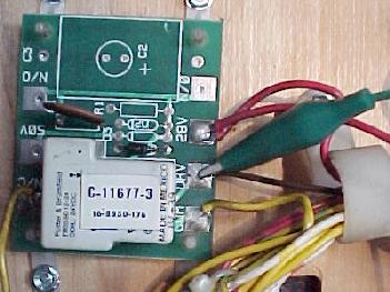
Robert Snicer's drawing of how early system 11 games handled the
higher voltage 50 volt coils, using a under the playfield relay
board.
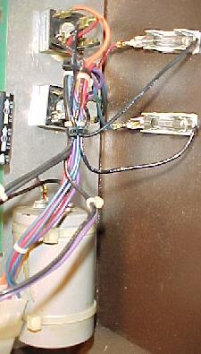
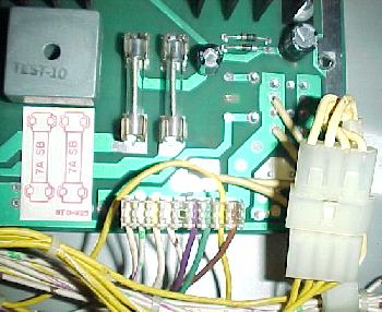
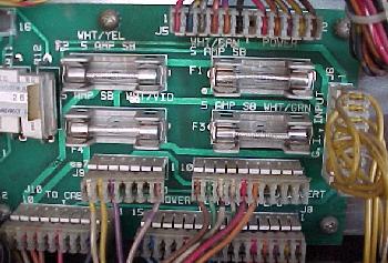
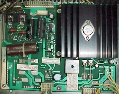
- Power Supply board.
The power supply board provides +5 volts for all circuit boards. It also produces the +100 and -100 volts for the score displays. It also acts as a liaison for the +18 volts for the lamp matrix (no circuit, just a fuse) and the general illumination (GI) on games before Banzai Run. The power supply board does some mild processing of the solenoid voltage too.
This particual power supply version was used from Big Guns to Cyclone,
because it lacks the relay in the lower right corner for the A/C
bank select, but still has the GI connectors (that were moved to
the Interconnect board on Banzai Run and later games).
- There were basically four different system 11 versions of the
power supply. The first version was D-8345-xxx (where xxx is the game
number). This was used from High Speed to Swords of Fury. On these
power supplies there are three different sub-versions of this board,
all with the same prefix (D-8345) number:
- High Speed to Fire! (no Auxiliary power supply board, no Interconnect board): has GI connectors and GI relay on the power supply board.
- Big Guns, Space Station, Cyclone (Auxilary power supply board, no Interconnect board): has GI connectors, but no GI relay (moved to the Auxiliary power supply board).
- Banzai Run, Swords of Fury (Auxiliary power supply board, Interconnect board): no GI connectors (moved to the Interconnect board), no GI relay (moved to the Auxiliary power supply board).
Starting with Taxi, a new power supply was used, number D-12246.
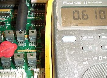
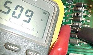
Low +5 volts from the Power Supply board.
A low +5 volts
coming from the power supply can often be attributed to the 47 mfd 50
volt capacitor at C8. If this cap fails, a low +5 volts will result.
If the large filter cap C10 (18,000 mfd 20 volts) wears out, this can
cause low or bad +5 volts also.
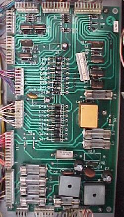
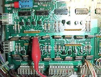
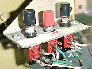
- System 11's Auxiliary Power Driver board.
- Bank select circuit and bank select relay.
- Bridge rectifiers that supply the solenoid power (previously these bridges were just bolted to the back of the backbox).
- Driver transistors (TIP36) for the 50 volt devices. This eliminated the small relay boards under the playfield. Up to eight TIP36c transistors can be used on this board. But if a game didn't use all eight, only the number used was actually installed!
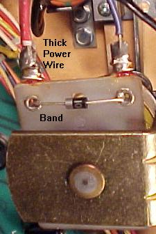
- Coil diodes. The coil diodes were no longer mounted on the coils themselves, but were instead installed on this board. This eliminated diodes breaking off the coils due to vibration. It also simplified coil replacement, as the operator no longer had to worry about which coil lead the diode's band was attached to on the coil.
- Solenoid fuses. The 50 volt solenoid fuses were mounted on this board.
Starting with Big Guns, system 11 games had an additional "auxiliary power driver" (APD) board. This board was used to hold the:
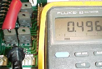
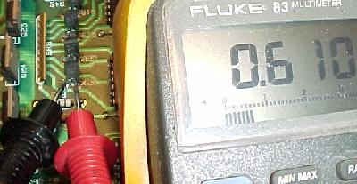
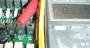
Zero Ohm "Resistors" on the Auxiliary power driver
board.
On many of the games with the new Auxiliary power driver
board, Williams used zero ohm resistors as jumpers on this board. The
reason they used these "resistors" was they could be automatically
installed into the circuit boards with production machines before
being wave soldered. Unfortunately, sometimes these zero ohm resistors
fail and go open. For this reason, system 11 games used actual wire
jumpers instead of these zero ohm resistors. Check W1, W3, W4 and W6
for open zero ohm resistors on the APDB.
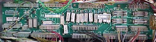
- The Interconnect Board.
Starting with Banzai Run, Williams started using an "interconnect board" inside the backbox (note the Banzai Run interconnect board is unique to other interconnect boards). Often this long, skinny board was mounted beneath the CPU board, or on the sides of the backbox. This board was a "truck stop" for lamps (GI, controlled, flashers), switch matrix, and coil power on the game. The lamp GI (general illumination) wiring from the playfield would come here, go through some fuses, and then continue on to the CPU board. This board also held the resistors for the flash lamps. At this time Williams dropped resistor R1 from the flash lamp circuit and only used R2 on the interconnect board. This greatly increased reliability because flash lamp resistor R1 (330 ohms 7 watts) failed quite often. The interconnect board also holds several MOC3010 opto-couplers for the flipper lane change circuit (games before the interconnect board did lane changes with a second switch on the flipper cabinet switch).
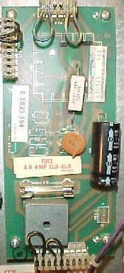
Flipper Power Supply board.
All system 11 games, Fire!
and before, have a small flipper power supply board to the right of
the CPU board. This board was basically a fuse, a bridge rectifier, a
resistor, and a few capacitors. It was used to provide power to the
flipper coils. When the Auxiliary power driver board (APDB) was
introduced in Big Guns, this board was combined into the APDB.
on games Fire! and before.
Flipper Differences.
Flipper coils are actually two coils
in one package. The "high power" side is a few turns of thick gauge
wire. This provides low resistance, and therefore high power. The "low
power", high resistance side is many turns of much thinner wire. This
side of the coil is important if the player holds the cabinet switch
in, keeping the flipper coil energized. The high power low resistance
side of the coil is only active when the flipper is first energized.
But when the flipper is energized and at full extension, the low
powered side of the flipper coil is used so the coil doesn't get hot
and burn.
Flipper worked different on games High Speed to Millionaire. These games used a series wound FL23/600-30/2600 flipper coil. The common lug (where both the low and high powered coil wires were connected together) on these flipper coils was the middle of the three lugs. Also these coils used ONE diode across the two outside lugs. The EOS switch on these games, when opened, enabled BOTH the high power and low powered coils together. This style of flipper coil did NOT use a 2.2 mfd anti-spark EOS capacitor. The problem with this series wound coil was the "back spike" of current that occured when the EOS switch was opened. This cause the EOS switch to excessively wear and pit.
- With the introduction of F-14 Tomcat, Williams changed to the
parallel wound FL11630 style flipper coil. This coil now used an
outside lug as the common lug (where both the low and high powered
coil wires were connected together). Also TWO diodes were used and
required on these flipper coils. This parallel wound coil eliminated
the "back spike" of current when the EOS switch opened. It also
allowed the use of a 2.2 mfd 250 volt capacitor to further limit EOS
switch sparking and pitting. Now when the EOS switch opens, this
removed the high powered side of the coil from the circuit. The low
powered side of the flipper coil is always in the circuit, but is
essentially ignored when the high powered side is in the circuit. This
happens because the current takes the easiest path to ground (the low
resistance, high power side of the coil). The low power high
resistance side of the flipper coil won't get hot if the player holds
the flipper button in.
- The CPU Board Flipper Relay K1.
The flippers are only enabled during game play and in diagnostic mode. The flipper enable relay is what turns the ground connected to the flippers off and on. This enable relay is located on the CPU board at K1, and is a 4P, 40 ohm, 6 volt relay. When you enter diagnostic mode, you should hear the flipper relay K1 click on (activating the flipper buttons).
Norbert Snicer's drawing of the flipper circuit used from F-14 and
later. Notice the CPU board relay K1 that energizes the flippers during
a game.