- On the top side of the playfield, make sure the bad switch contacts haven't been bashed together by an errant air pinball.
- If it's a micro-switch, check the actuator arm. Make sure it's adjusted properly. Listen for the micro-switch's "click" when activating. No click usually means the switch is mis-adjusted or broken.
- Check that the wires going to the switch are soldered well, and haven't fallen off.
- Check the continuity (using your DMM's continuity setting) of the wire between this switch and another working switch in the same column (white wire) or row (green wire).
- If it's a blade or leaf style switch, check the contacts for proper closure. Clean the switch contacts with a business card (do NOT use a file as the contacts are gold plated). Put the card between the contacts, close the contacts, and pull the card through the contacts. This is all that is needed to clean gold plated switch contacts.
- Check the switch to make sure it works. Use your DMM's continuity setting, and put one lead on the "common" lug (the lug to which the banded end of the diode connects) of the switch. Put the other lead on the green (normally open) switch lug. Your meter should only beep when the switch is activated, and not beep when the switch is de-activated. Move the DMM's lead from the green to the white wire (normally closed) switch lug. Your meter should beep when the switch is de-activated, and NOT beep when activated.
- Check the diode on the switch. Make sure the diode is connected properly, and is working (see below).
- Check other switches in that switch's row or column. Two 4041 chips control rows, and 2N3904 transistors and 74LS244 at U40 control columns. Both rows and columns are controlled by a 6821 PIA at U38.
- Disconnect the middle green (ground) wire from the switch. It should have a quick connector. If the middle green ground wire is soldered to the switch, ignore this test and do the above "fail-safe" diode test.
- Put your DMM on diode setting.
- Connect the black lead of your DMM to the diode's banded side, and the red lead to the non-banded side.
- Activate the switch.
- You should get a reading of .4 to .6 on the meter.
- Reverse the DMM's leads (red lead to the diode's banded side), and keep the switch activated. You should get a null meter reading.
- Leave the leaf switch's diode and all wires connected.
- Make sure the switch isn't activated.
- Put your DMM on diode setting.
- Connect the black lead of your DMM to the diode's banded side, and the red lead to the non-banded side.
- You should get a reading of .4 to .6 on the meter.
- Reverse the DMM's leads (red lead to the diode's banded side). You should get a null meter reading.
- Pin 1 = Column 1, green/brown
- Pin 2 = Column 2, green/red
- Pin 3 = Column 3, green/orange
- Pin 4 = Column 4, green/yellow
- Pin 5 = Column 5, green/black
- Pin 6 = key
- Pin 7 = Column 6, green/blue
- Pin 8 = Column 7, green/violet
- Pin 9 = Column 8, green/gray
- Pin 1 = Row 8, white/gray
- Pin 2 = Row 7, white/violet
- Pin 3 = Row 6, white/blue
- Pin 4 = key
- Pin 5 = Row 5, white/green
- Pin 6 = Row 4, white/yellow
- Pin 7 = Row 3, white/orange
- Pin 8 = Row 2, white/red
- Pin 9 = Row 1, white/brown
- Remove the backglass and fold down the display to gain access to the CPU board.
- Unplug the connectors at 1J8 and 1J10 (bottom portion of the CPU board).
- Turn the game on.
- After the game boots, go to the Test menu's "Switch Levels" test.
- Connect your alligator test lead to pin 9 of 1J10. Pin 9 is the left most pin, as facing the board.
- On the other end of the alligator test lead, clip on a 1N4004 diode, with the banded end away from the alligator lead. Touch the banded end of the diode to pin 1 of 1J8. Again, pin 1 is the right most pin, as facing the board.
- The display should show switch 1 is closed.
- Move the diode/alligator lead on 1J8 to the next pin. The display should show switch 9 is closed.
- Repeat the previous step, until pin 9 of 1J8. Switches 1, 9, 17, 25, 33, 41, 49, 57 should be closed on the display as you move forward, pin 1 to pin 9, on connector 1J8. Note pin 6 is a key pin, and should be skipped.
- Remove the backglass and fold down the display to gain access to the CPU board.
- Unplug the connectors at 1J8 and 1J10 (bottom portion of the CPU board).
- Turn the game on.
- After the game boots, go to the Test menu's "Switch Levels" test.
- Connect your alligator test lead to pin 1 of 1J8. Pin 1 is the right most pin, as facing the board.
- On the other end of the alligator test lead, clip on a 1N4004 diode, with the banded end towards the alligator lead. Touch the non-banded end of the diode to pin 1 of 1J10. Again, pin 1 is the right most pin, as facing the board.
- The display should show switch 1 is closed.
- Move the diode/alligator lead on 1J10 to the next pin. The display should show switch 2 is closed.
- Repeat the previous step, until pin 9 of 1J10. Switches 1, 2, 3, 4, 5, 6, 7, 8 should be closed on the display as you move forward, pin 1 to pin 9, on connector 1J10. Note pin 4 is a key pin, and should be skipped.
- Remove the backglass and fold down the display to gain access to the CPU board.
- Turn the game on.
- After the game boots, go to the Test menu's "Switch Levels" test.
- Unplug the connectors at 1J8 and 1J10 (bottom portion of the CPU board).
- With your logic probe connected to power and ground, probe each pin 1 to pin 9 of 1J8 (pin 1 is the right most pin, as facing the board). These are the switch columns. All pins should show PULSE on the logic probe.
- With your logic probe connected to power and ground, probe each pin 1 to pin 9 of 1J10 (pin 1 is the left most pin, as facing the board). These are the switch rows. All pins should show HIGH on the logic probe.
3k. When things don't work: the Switch Matrix
- Switches on any pinball game are very important. On electronic
games, when a switch closes, it informs the CPU to score points, award
a feature, and/or to activate a solenoid. If a switch is stuck closed,
the CPU will ignore this switch (in most cases).
If a switch is not activated in 30 games, or is permanently closed, the switch is assumed to be bad. This will create a test report, which is shown when the game is turned on. If a particular feature of a game is difficult to score, it's associated switch may be (falsely) assumed bad (if not activated in 30 games). To correct the test report, remove the playfield glass, and activate the switch by hand within a game, or within the diagnostics switch edge test.
All switches on a system 11 game (except for the direct switches at connector 1J14, which are only the test button switches) are in the "switch matrix". The switch matrix is controlled by eight switch columns, and eight switch rows. The cross-section of any row and column designates any one of the potential 64 different switches. The switch columns are controlled through CPU board connector 1J8, which connects to 2N3904 transistors Q42-Q49. The output of these goes to a 74LS244 chip on the CPU board at U40. The output of this chip then goes to a 6821 PIA at U38. The switch rows are controlled through CPU board connector 1J10, which connects to 4011 chips at U30 and U39. This then connects to the same 6821 PIA at U38.
Test Button Switches.
On system 11 games, the test button
switches inside the coin door only are wired directly to the CPU board
at connector 1J14. These switches do not go through the switch
matrix on any system 11 revision. The test button switches are direct
switches to the CPU board, which directly to the CPU. The diagnostic
switch connects to the CPU's NMI line. Williams did this so if there
is a switch matrix short, you can still get into the game's diagnostic
tests without using any switches in the switch maxtrix.
Shorting the Switch Matrix to +50 volts.
When in a hurry,
many make an under playfield adjustment with the game turned on. Doing
a switch adjustment with the power on could easily short a coil lead
(+25/50 volts) to a switch lead. This will immediately blow the switch
matrix, and fry the most anything to and including the 6821 PIA at
U38. You can bet the switch row 4011 chips at U30 and U39 will have
failed. Also it could take out the switch column 2N3904 transistor(s)
and the 74LS244 chip at U40.
If after replacing the suspect components, disconnect the switch input plugs from 1J8 and 1J10 at the bottom of the CPU board. Put the game into switch test mode, and none of the switches should be activated! If a whole row of switches is activated, that would mean that something in the row chain is still bad.
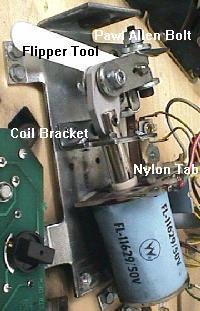
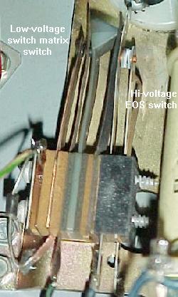
Shorting the Flipper EOS switch to the Lane Change
switch.
Williams has a feature called "lane change" in many of
their games. This allows the player to change the lit lanes using the
cabinet flipper buttons. Prior to Banzai Run, this is done by doubling
up a second switch on the flipper EOS switches. The EOS switches are a
+50 volt switch. The lane change switch is a +5 logic switch connected
to the switch matrix. These two switches are insulated from each other
by a small nylon "triangle" activator. But if these two switches
touch, the switch matrix will burn (as described above).
When adjusting or cleaning the flipper EOS switches or lane change switches, make sure the game is turned OFF. This will prevent shorting these two switches together. Also, do not clean the smaller lane change switch with anything other than a business card.
Lane Change on games with Interconnect boards.
When the
interconnect board was introduced on Banzai Run, Williams stopped
using a doubled up switch on the flipper EOS switches for the lane
change. Instead, circuitry was added on the interconnect board using a
MOC3010 opto coupler. If you have problems with the lane change on
these games, replacing the small eight pin MOC3010 opto couplers will
usually fix the problem.
Switch Numbering.
Each switch has a number associated
with it. Unlike WPC, system 11 switches are just numbered 1 to 64.
There is no relationship to what row or column number the switch
number is (on WPC, switch 43 is column 4 row 3, for example). On
system 11 games, switches 1 to 8 are column 1, rows 1 to 8. Likewise,
switches 9 to 16 are column 2, rows 1 to 8. This continues up to
switches 57 to 64, which are column 8, rows 1 to 8.
in the "down" position (as shown here). If the center
button is "up", you will enter the audits menu instead.
- Using the Internal Switch Tests.
To test switches, use the internal test software. Press the center red button inside the coin door down, then press the black button closest to the coin door. Finally, press the center button again. The button closest to the coin door will take you from test to test. Go to the "switch level" test and activate any switch on the playfield using a pinball (this simulates real game play), and it should show on the game's display.
If a Bad Switch is Found.
If a switch does not work,
check these things:
If the switch is bad, replace it. If all the switches are bad in a particular switch column or row, start replacing components closest to the switch.
- Phantom Switch Closures: a Shorted Switch.
It's a strange problem. You're playing a game, and when the ball goes down the right inlane, the left slingshot fires! Or when you make a ramp shot, the game slam tilts. One switch closes, but a completely unrelated event than occurs.
This is a classic problem of a shorted switch. It confuses the switch matrix into thinking something else has occurred. This can happen from an "air" pinball, that bashes an above playfield switch's contacts together, causing a short. Also a bad switch diode can do this too. In either case, you need to find the shorted switch. Unfortunately, it won't be obvious. The switch matrix is confused, so any diagnostics the game provides will be of limited help.
First, try and find the switch that causes something unrelated ("phantom") to happen. Take the playfield glass off, and start a game. Activate the switches with your hand, and find the switch which activates the phantom (unrelated) switch. Once you have found the switch, go to the game manual and find the switch's number, row number, and column number. Say for example, switch 53 (column 7, row 5) is causing the phantom closure. Now you need to get the other three switches that make up the "square" of this row and column. First get the reverse switch number, switch 39 (column 5, row 7). Then get the other two switches: switch 37 (column 5, row 5), and switch 55 (column 7, row 7). Your switch short will probably be one of these four switches.
If you are having problems figuring out if the short is in the playfield or the CPU board, try this. Remove connectors 1J10 and 1J8 from the CPU board. Then put the game in switch edge test. Using the manual, find which row and column of the switch that is causing the phantom closure. Then cross this row and column directly on the CPU board (with wire and alligator clips, and a diode, as described below in the "testing the switch columns/rows"). The row and column numbers for each pin of connectors 1J10 and 1J8 are listed below. If the phantom switch does not activate, the problem is in the playfield. If the phantom closure still works, you have a CPU board problem.
If your phantom switch problem is on the CPU board, don't forget to look at the 1k ohm resistor pack SR10 on the CPU board. When this resistor pack goes bad, it can cause intermittent phantom switch closures. Use your ohm meter, and test the resistor pack. If in doubt, just replace it.
Bad Switch Diode.
Each micro-switch on the playfield also
has an 1N4004 diode soldered to it. This diode can short closed. It
doesn't happen often though. Important: If a switch diode does
short closed, all switches in that particular column or row will
exhibit strange behavior. If a switch diode goes permanently open, the
switch will never register. Keep this in mind when diagnosing switch
matrix problems.
Fail-Safe Diode Test.
With the game off, use your DMM set
to diode position. With the black lead on the banded side of the
diode, you should get a .4 to .6 volt reading. Reverse the leads, and
get a null reading. If the diode test bad, cut one lead of the diode
from the switch to remove it from the circuit, and test it again just
to make sure the diode is really bad. Reconnect the diode after
testing, or replace it if bad.
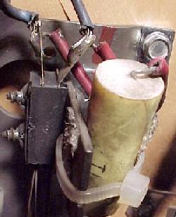
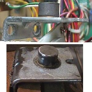
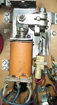
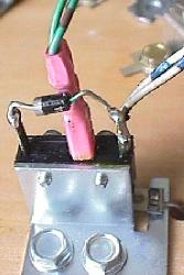
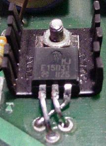
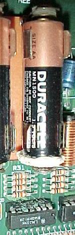
Testing a switch diode on a microswitch without removing
the
diode. Not the screw driver keeps the switch activated, and
the
middle green wire (ground) has been disconnected.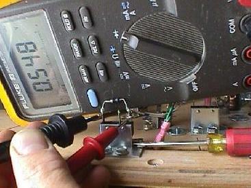
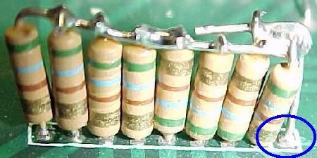
- Testing a Microswitch's Diode, without removal.
You can test the diode on a microswitch without unsoldering a diode lead from the switch. This technique assumes the switch is wired in the standard configuration: green (ground) wire to the center lug, the banded end of the diode to the far switch lug, and the non-banded diode lead and the switch wire(s) to the close switch lug (as shown in the pictures above).
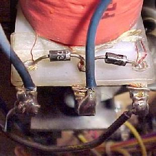
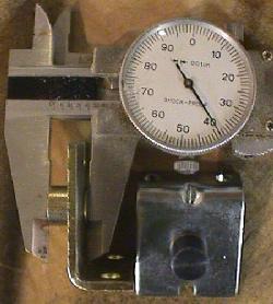
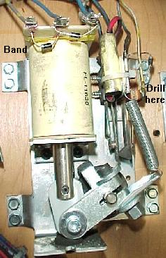
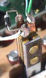
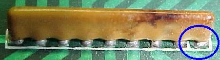
Testing a Blade/Leaf Switch's Diode.
Testing the diode on
a leaf switch is far easier. No wires need to be disconnected, and the
switch should not be activated. This technique assumes the switch is
wired in the standard configuration: green (ground) wire to the center
lug, the banded end of the diode solo, and the non-banded diode lead
and the switch wire(s) to the other switch lug (as shown in the
pictures below).
Testing a switch diode on a blade/leaf switch, without
removing the diode. The switch doesn't need to be
activated, and
no wires need to be disconnected.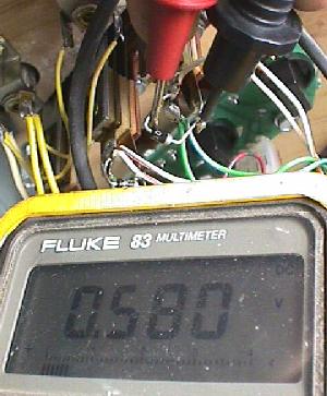
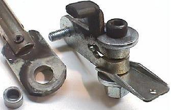
- Installing a New Switch Diode.
You can replace the diode with a 1N4004 (or 1N4002 or 1N4001) diode. Make sure you install the new diode with its band in the same orientation as the old diode (assuming it's correct!). If you're unsure, compare the diode's band orientation to a working switch and diode. Most (but not all!) switches have the green (ground) leads connected to the center (normally open) lead of the switch. Then the row (white) wire is connected to the switch lead closest to the center lead (the normally closed lead). The banded end of the diode is connected solo to the far (common) switch leg, and the non-banded end is connected to the same leg as the row (white) wire. There are some exceptions to this mounting. Your game manual will specify any non-standard switch installations.
On a micro-switch, the ground (green) wire usually goes to the center
lug, the "live" wire and the non-banded side of the diode to the lug
closest to the center. The band on the diode goes to the solo,
far third switch lug. The leaf switch uses the same connection method
(ground to center, banded end of diode solo). Note there are some
exceptions to this mounting.
- Switch Matrix Row or Column Problem: the Easy Test.
If you are getting an error message that you have a switch matrix row or column problem, you need to determine if this is a CPU board problem or a playfield problem. The easiest way to do this is to unplug the switch matrix row and column plugs at 1J10 and 1J8. Now enter the game's diagnostics (coin door center red button down, press the black button closest to the coin door), and go to the switch edge test. If the row or column problem is gone (no switch reports), you have a problem in the playfield wiring. If the problem is still there, you have a problem on the CPU board. Note most shorted switch matrix problems are caused by a bad switch matrix column 2N3904 transistor at Q42-Q49 (which affects the entire column).
Switch Matrix Plug and Pin Numbers.
If you are doing
intensive switch matrix diagnostics with the plugs removed at 1J10 and
1J8, you may want to simulate an actual playfield switch closure,
without using the playfield! This can be done by using the internal
switch edge test, and an alligator lead connected to the particular
row/column (switch) in question, and a diode (as described above).
1J8 Switch Column Pin Numbers
1J10 Switch Row Pin Numbers
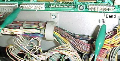
the test lead is attached to pin 9 of 1J10, and is stationary. The
other clip holds the non-banded side of the diode. Then the banded
side of the diode is touched to each pin of connector 1J8. The
"switch levels" test should indicate switches 1, 9, 17, 25, 33, 41, 49, 57
when moved from pin 1 to 9, respectively.
- Testing the Switch Columns (all system 11 revisions).
To test the switch columns, do the following:
If a particular column number does not display as closed, or is closed without any test lead connection, there is a problem on the CPU board. Usually this is a bad switch matrix column 2N3904 transistor at Q42-Q49.
Testing the switch matrix rows: Using a diode and a test
lead,
the test lead is attached to pin 1 of 1J8, and is stationary.
The
other clip holds the banded side of the diode. Then the
non-banded
side of the diode is touched to each pin of
connector 1J10. The
"switch levels" test should indicate switches 1,
2, 3, 4, 5, 6, 7, 8 when activated.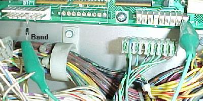
- Testing the Switch Rows (all system 11 revisions).
To test the switch rows, do the following:
If a particular row does not display as closed, or is closed without any test lead connection, there is a problem with the CPU board.
Testing the Switch Matrix Columns and Rows with a Logic
Probe.
If you have a logic probe, you can use this to easily
test the switch matrix:
Resistor Network Testing/Explaination used in the Switch
Matrix.
The resistor networks in the switch matrix can fail,
and this is fairly common. There are two types of resistor networks
used on the system 11 CPU board; "Bussed" and "Isolated".
If a resistor network is "560 x 8" and has 9 pins, that means it's BUSSED; all the resistors are tied to one common pin (this pin is labeled with a white square around it on the circuit board). Simply put, if a resistor network has an odd number of pins, it is probably bussed.
If a resistor network is "1K x 4" and has 8 pins, this is an ISOLATED resistor network; a bunch of resistors in the same small package, so it uses two pins per resistor. Simply put, if a resistor network has an even number of pins, it is probably isolated.
| Left: A bussed resistor network. Right: An isolated resistor network. |
  |
- SR11: 560 ohms x 8, bussed, used for the switch returns (rows).
- SR14: 3.3k ohms x 8, bussed, used for the opto switch returns (rows).
- SR9/SR10/SR12/SR13: 1k ohms x 4, isolated, used for the switch returns (rows).
- SR15: 4.7k ohms x 8, bussed, used for the switch drives (columns).
- 1k x 4 issolated (4 elements): Q4102-ND
- 1k x 8 bussed (9 elements): Q9102-ND
- 4.7k x 8 bussed (9 elements): Q9472-ND
- 560 x 8 bussed (9 elements): Q9561-ND
- 3.3k x 8 bussed (9 elements): Q9332-ND
- 1J8 pin 1, to Q45, to R77, to SR15 pin 2, to U40 pin 18 (column 1).
- 1J8 pin 2, to Q49, to R78, to SR15 pin 3, to U39 pin 3 (column 2).
- 1J8 pin 3, to Q44, to R75, to SR15 pin 4, to U39 pin 16 (column 3).
- 1J8 pin 4, to Q48, to R76, to SR15 pin 5, to U39 pin 5 (column 4).
- 1J8 pin 5, to Q43, to R73, to SR15 pin 7, to U30 pin 14 (column 5).
- 1J8 pin 6: KEY
- 1J8 pin 7, to Q47, to R74, to SR15 pin 8, to U30 pin 7 (column 6).
- 1J8 pin 8, to Q42, to R71, to SR15 pin 9, to U30 pin 12 (column 7).
- 1J8 pin 9, to Q46, to R72, to SR15 pin 10, to U30 pin 9 (column 8).
- 1J10 pin 1, to SR11 pin 2, to SR10 pin 1, to U39 pin 12 (switch row 8).
- 1J10 pin 2, to SR11 pin 3, to SR10 pin 3, to U39 pin 8 (switch row 8).
- 1J10 pin 3, to SR11 pin 5, to SR10 pin 5, to U39 pin 2 (switch row 6).
- 1J10 pin 4: KEY
- 1J10 pin 5, to SR11 pin 6, to SR10 pin 7, to U39 pin 5 (switch row 5).
- 1J10 pin 6, to SR11 pin 7, to SR10 pin 2, to U30 pin 13 (switch row 4).
- 1J10 pin 7, to SR11 pin 8, to SR10 pin 4, to U30 pin 9 (switch row 3).
- 1J10 pin 8, to SR11 pin 9, to SR10 pin 6, to U30 pin 2 (switch row 2).
- 1J10 pin 9, to SR11 pin 10, to SR10 pin 8, to U30 pin 6 (switch row 1).
- Switch column shorted to ground.
When a column wire is shorted to ground, and any switch in that column is closed, the switch test will show ALL switches in the ROW of the closed switch as being closed. If no switches are closed, the switch test will show no switches closed. To find the location of the short, go to the end of the switch column wire on the playfield (the switches are "daisy chained" together for an entire column or row). Then break the daisy chain one switch at a time until the short no longer shows in the switch test. - Row shorted to ground (diode anode).
When the anode (non-banded end of the switch diode) is shorted to ground, the switch test will show the entire row as activated (whether any switches are closed or not). To find the location of the short, go to the end of the switch row wire on the playfield (the switches are "daisy chained" together for an entire column or row). Then break the daisy chain one switch at a time until the short no longer shows in the switch test. - Row shorted to ground (diode cathode).
When the cathode (banded end of the switch diode) is shorted to ground, that switch's entire row will show as closed in the switch test (whether the switch is open or closed). To find the location of the short, go to the end of the switch row wire on the playfield (the switches are "daisy chained" together for an entire column or row). Then break the daisy chain one switch at a time until the short no longer shows in the switch test. - Column wires shorted together.
When two column wires are shorted together, and none of the switches in those columns are closed, the switch test will show no problems. But pressing any switch in either column will show that switch, along with a switch in the column that is shorted on the row of the switch you are closing. For example, if column 2 and column 4 are shorted together, closing switch column 2 row 3 will also show a closed switch in column 4 row 3. - Row wires shorted together.
When two row wires are shorted together, and no switches are closed, the switch test will show no closed switches. When any switch on either row is closed, another switch on the same column as the closed switch will also show as closed. For example, if rows 1 and 4 are shorted, closing a switch in row 1 column 3 will also show a closed switch on row 4 column 3. - Column and row wires shorted together.
When a column and row wire are shorted together, the switch test will show the switch that is at the intersection of the row and column as being closed, even though it is not closed. All other switches on all other rows and columns will work correctly. For example, column 1 and row 3 are shorted together. The intersection of this column and row will show that switch as closed (even if it's not). And remember, this switch is not what is causing the problem! - Open diode on a switch.
An open diode on a switch will cause only that switch not to work. - Shorted diode on a switch.
A shorted switch diode will show no problems when only that switch is opened or closed. However if additional switches in that row or other columns are closed, false switch readings can be shown. - Micro-switch: no maintenance required. Can adjust the actuator arm only by rotating the switch in its bracket. Do not BEND the activator arm! Loosen the two screws holding the switch, and rotate the switch to adjust the activator arm. Re-tighten the screws, but not too tight as it will bind the switch mechanism.
- Blade or Leaf switch: clean with a business card inserted between the contacts. Squeeze the contacts closed, and remove the business card. Do not use a file on these gold plated contacts! Re-adjust the contact spacing for correct operation.
- Opto switches: use a Q-Tip and some Windex. Dip the Q-tip in the Windex, and clean the opto's two LED's (receiver and transmitter) with the Q-tip.
- 3J5 pin 1: ground
- 3J5 pin 3: -100 volts DC
- 3J5 pin 4: +100 volts DC
- 3J5 pin 6: +5 volts DC
- 3J2 pin 1 (orange): -100 volts DC
- 3J2 pin 3 (brown): +100 volts DC
- 3J2 pin 5 (black): ground
- 3J2 pin 6 (gray): +5 volts DC
- J307 pin 1: input +100 volts DC
- J307 pin 4: ground
- J306 pin 1: +5 volts DC
- J306 pin 3: ground
- Q1 = MJE15030 transistor. On older games that specify a SDS201 transistor (which is no longer available), the leads of the MJE15030 transistor must be "twisted" so the emitter, base and collector match the circuit board. You can also use a MJE340 (NPN 300 volt transistor) or a 2N3440 with a "star" heat sink.
- Q2 = 2N5401 (PNP 150 volt transistor).
- Z1 = 1N4730A (3.9 volt 1 watt diode).
- ZR2 (Z2) = 1N4764A (100 volt, 1 watt) diode. Use 1N4763A (91 volt, 1 watt) diode instead (to increase score display life).
- R1 = 39k ohm, 1 or 2 watt flame proof resistor.
- R2 = 680 ohm, 1/2 watt resistor.
- R3 = 330k ohm, 1/2 watt resistor.
- C2 = 0.1 mfd 250 volt metal polyester capacitor.
- Q3 = MJE15031 transistor. On older games that specify a SDS202 transistor (which is no longer available), the leads of the MJE15031 transistor must be "twisted" so the emitter, base and collector match the circuit board. You can also use a MJE350 (PNP 300 volt transistor) or a 2N5416 with a "star" heat sink.
- Q4 = 2N5551 (NPN 140 volt transistor).
- Z3 = 1N4730A (3.9 volt 1 watt diode).
- ZR4 (Z4) = 1N4764A (100 volt, 1 watt) diode. Use 1N4763A (91 volt, 1 watt) diode instead (to increase score display life).
- R4 = 39k ohm, 1 or 2 watt flame proof resistor.
- R5 = 680 ohm, 1/2 watt resistor.
- R6 = 330k ohm, 1/2 watt resistor.
- C4 = 0.1 mfd 250 volt metal polyester capacitor.
- Here are the different resistor networks used in the system 11
switch matrix:
When testing a BUSSED resistor network, first find pin 1. This pin will have a white square around it, to isolated it from the rest of the pins. Use a DMM set to ohms, and put one lead on pin 1. Put the other lead on each pin 2 to 9. The same reading should be seen for each pin 2 to 9.
When testing an ISOLATED resistor network, put the DMM leads on the two adjacent pins furthest to the right or left, and note the reading. Then move both DMM leads down one pin. The same value should be seen. Continue down the resistor, moving both DMM leads one pin at a time, until all adjacent pins are tested.
| A bussed
resistor network. Note the white square around pin 1; this is the common pin. |
|
| A "hacked"
bussed resistor network. If the correct resistor network can not be found, this shows how to make a bussed resistor network from individual resistors. Note the white square around pin 1; this is the common pin. This picture shows quite well how a bussed resistor network is wired. |
|
- Replacment resistor networks can be purchased from Digikey (http://www.digikey.com/). Below are
the part numbers:
Bad Switch Column: How to Fix it.
Usually the switch
column transistors fail here. These are 2N3904 transistors at Q42 to
Q49. See the Checking
Transistors section for details on testing these transistors.
Right before the transistors there is a capacitor network; this rarely
fails (and is not documented in the list below). Next each one of the
eight transistors connects to a 1.5k resistor at R71 to R78. Then the
resistors at R71 to R78 connect to a resistor network at SR15. This is
a group of eight separate 4.7k ohm resistors, in a single package.
Measure the resistance between pins 2 to 10 of SR15, and pin 1 of SR15
(the common pin). You should get 4.7k ohms for each connection:
Bad Switch Row: How to Fix it.
First check the 560 ohm
resistor network at SR11. This is a group of eight separate 560 ohm
resistors, in a single package. Measure the resistance between the
pins 2 to 10 of SR11, and pin 1 of SR11 (the common pin). You should
get 560 ohms for each connection. Then check the 1k ohm SR10 between
the SR11 pin and the stated pin on U39/U40 below. You should get 1k
ohms for each connection:
Further Diagnosing of the Switch Matrix.
If you are
having a switch matrix problem, the first plan of attack is to do the
above column and row switch matrix tests. If these tests pass, the
problem most likely is in the wiring. Note most switch failures show
as Row failures (even though it could be a column problem). Here are
eight different ways the switch matrix can fail. All require you use
the internal "switch level" or "switch edge" tests of the game.
Switch Maintenance.
Here are the procedures for
maintaining your WPC switches:
What is that loud "Popping" when I turn my Game On?
"I
have this problem when I power-on my game; the free game knocker
'pops' with a loud knocking 4 or 5 times, then finally stops and the
game starts up and does appear to play correctly. I get a message at
the beginning when this happens to 'adjust switch outside loop' and
#35 shows up in my fourth player score display."
What the game is trying to tell you is that switch #35 has not been actuated (ie: closed) in about 30 games or so. That's usually sufficient reason to suspect that the switch as bad. The game will do its best to compensate for the bad switch (by using other switches around it), but it is trying to say that the switch needs to be looked at.
Inside the coin door there should be three operator diagnostic test switches. Make sure the middle one is in the "Down" position, and then press the one marked "Advance" or "Enter". This puts the game in Test mode. Keep pressing Advance until you see the "Switch Edges" test (remember at this point the playfield is "live", so watch those pop-bumpers, slingshots and flippers). Now verify that the bad switch really doesn't work by activating it. Test it using the ball if possible and not just your hand.
Now turn the game off and remove the balls and lift the playfield. Locate the switch under the playfield. There should be a bunch of "blade" (or possibly micro) switches. The one that doesn't work may have a broken wire, or some other sort of mechanical failure. If it is a leaf switch, it may simply be dirty. Find a business card and gently press the switch leafs closed, and pass the card between the two contacts. These switch contacts should be gold flashed, so don't use anything abrasive (the business card is all that is needed).
The leaf switch could also be out of adjustment. There is one moving blade, and one stationary blade. To adjust the switch, bend the *stationary* blade only to move the switch contacts closer. Test the switch with a ball to make sure it is working correctly.
If the game has microswitches, a simple adjustment to the activator arm may be in order, or the switch itself has failed.
Test the switch again in switch test, and see if this solves the problem. If it doesn't, check for a problem with a broken wire on a nearby switch. The switch wires "daisy chain" from switch to switch in the same row/column. So a non-working switch could be a broken wire "upstream".
3L. When thing don't work: Infrared Optic Switches (Drop Target switches)
Williams also used optic light emitting diodes (LED's) for some switches, even on the older System 11 games. Mostly Williams used "U" shaped optics for detecting the position of drop targets. The problem with this is vibration. Often the optics will actually break off the circuit board because the drop targets take so much abuse.
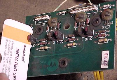
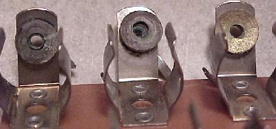
- If a drop target is not sensing when it is down, it's a good
chance you have an optic problem. The optic board is held to the drop
target with three "E" clips on rubber mounts. Remove the "E" clips and
the board will lift off the drop target assembly. Now inspect the
optics. If they are not broken, clean them with a Q-tip dipped in
Windex. It is amazing how often just cleaning optos in this manner
fixes them.
Optos have two sides to them: a transmitter, and a receiver. The transmitter is the part that fails 95% of the time. Essentially the transmitter is a light bulb, and all light bulbs burn out eventually. And the optics are always "on", even when the game is in attract mode (another good reason to turn your game off when not in use).
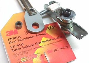
A nice tool to have in your tool box is the Radio Shack infrared detector card. This $5 credit card sized card will show if the optic transmitter is producing light. Without this card, you can not see this wave length of light. So this handy little card is quite good to have. Remember you must have the card positioned in front of the transmitter to see the light on the orange colored band (having it in front of the receiver won't show anything!). The "red" side of the "U" shaped opto is the transmitter side of the optic.
System 11b and Later Optic boards.
With system 11b, the
optic circuit was removed from the CPU board. This meant that the
optic board (for example on drop targets) needed added circuitry to do
the switch processing. This was done by adding LM339 chips to the
optic board. If you are having problems with an optic board, and you
know the optics themselves are good, suspect the LM339 chips. These
are inexpensive chips; just replace them wholesale on the optic board
if in doubt.
New Style Optics on Optic boards with LM339 Chips.
The
optics themselves were changed on the newer optic boards with LM339
chips. The new optics used new style "U" shaped optics (as used in the
1990 and later WPC games). Unfortunately this new style of optics had
a much bigger problem with breaking leads, and falling off the optic
board. Whenever replacing these optics, put a dab of silicone
underneath the optic when mounting them to help prevent this problem.
Replacing the Optics.
Be careful installing new optics.
It DOES matter which way you install them! If you install the new
optic backwards, you will probably ruin it. Remember on the old style
optic boards, the red side of the optic is the transmitter. On new
style optics, the side of the optic with the white "dot" or the
"notch" is the receiver. The white dot on these new style optics
matches with a corresponding white dot on the circuit board, to make
installation easy. Also use a dab of silicon under the optic when
mounting them. This will give them some shock resistance.
3m. When thing don't work: Score Display Problems
One of the most frequent system 11 problems relates to non-working or weak score displays. Fortunately, often there is a very easy fix for this problem.
The simplest thing to check when the score displays do not work is the +100 and -100 volt DC power section of the power supply. If either of these voltages are bad, your displays will not work. And quite often, this power supply section does go bad.
The 39k ohm Power Supply Resistors.
The major villain in
the system 11 power supply is resistors R1 and R4. These are both 39k
ohm, 1 watt resistors. Very often either or both of these resistors
will go out of spec, or even completely open. This will prevent the
+100 and/or -100 volts from getting to your score displays On newer
WPC games with alphanumeric displays, these are resistors R48 and R49
on the alphanumeric display board.
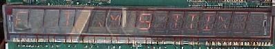
Here is the same score display after the 39k resistors were
changed on the power supply board. This cheap 50 cent fix shows that the
score display glasses themselves were good!
- If your high voltage fuses are not blown, and your score displays
do not work, first replace the 39k ohm resistors. These are cheap and
easy parts to replace (a lot cheaper and easier than replacing score
display glass!). Or at least check these. Replace these two resistors
with "flame proof" 1 or 2 watt 39k ohm versions. And make sure you
mount the new resistors slightly off the circuit board, so air can get
under them for cooling.
Check the +100/-100 volts at the Power Supply board.
It's
really easy to check the +100 and -100 volts at the power supply
board. These voltages should be from 95 to 105 volts. Check for these
voltage at power supply connector.
Power Supply D-8345-xxx (where xxx is the game number). Used from High Speed to Swords of Fury ??.
Power Supply D-11883 and D-12246. Used from Taxi ?? to Doctor Dude.
WPC AlphaNumeric Display Board. Used on Funhouse, Harley Davidson, the Machine.
Power Supply Diodes Leak.
Like resistors the two 39k ohm
resistors, the two diodes at D1 and D3 (1N5990) can start to "leak"
(on WPC alphanumeric games, diodes D1 and D2 on the alphanumeric
display board). If your displays are weak and your 100 volt section is
low (even with the score display glass unplugged), try changing these
two diodes (after you change the 39k ohm resistors first).
Blown high voltage score display Fuse(s) in the
Backbox.
Every system 11 game at least one fuse to protect the
+100 and -100 voltages which power the score displays. Later games
have more than one fuse. These are located in fuse holders in the
backbox. If these fuse(s) are blown, try replacing them, and power the
game back on. If they blow again immediately, you will probably need
to rebuild the high voltage section of the power supply board.
Also a blown UDN7180 chip on the master display board can cause the high voltage fuse(s) to blow on the power supply board. These chips can short the +/- 100 volts directly ground, and blow the fuse.
Increasing Score Display Life.
Glass score displays are
getting very expensive. Because of this, it is important to make your
current glass score displays last as long as possible. The best way to
do this is to decrease the 100 volts (which powers the displays) to 91
volts. This can be done by replacing the zener diodes at ZR2 (Z2) and
ZR4 (Z4) to a lower voltage diode
The original diodes used at ZR2, ZR4 are 1N4764A. These are 100 volt, 1 watt zener diodes. If you replace these with 1N4763A diodes, which are 91 volt, 1 watt zener diodes, only 91 volts (instead of 100 volts) will power the displays. This will make your displays slightly less bright, but it will also DRAMATICALLY increase their life span! Since glass score display tubes are becoming so expensive, this is highly recommended. Note on the newer WPC alphanumeric games, diodes D5 and D6 were changed to 1N4763 diodes from the start.
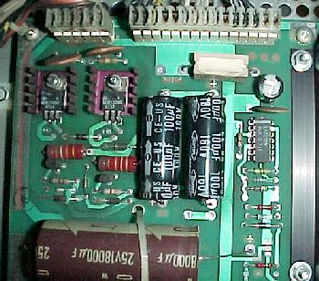
- Rebuilding the 100 volt Power Supply Section.
If any of the high voltage fuses are blowing, you probably need to rebuild the 100 volt power supply section. You will need to replace the following parts on the power supply board.
Positive System 11 100 volt section parts to replace:
Negative SYstem 11 100 volt section parts to replace
power supply. The leads on the MJE15030 and
MJE15031 must be "twisted" to replace the
older SDS201 and SDS202 transistors. This should
ONLY be done on power supplies that originally
used the older SDS201 and SDS202 transistors.
- When installing the new parts, cut the old parts out first. Then
use a solder sucker and clean out the circuit board holes. Make sure
you install new resistors slightly off the board, to allow for air
circulation. Solder all parts on both sides of the board.
When installing the newly fixed board, measure the output voltages BEFORE you plug in the connectors going to the score displays! Output voltage should be between 95 and 105 volts.
Score Display Ribbon Cable Problems.
System 11 and WPC
alphanumeric games have a fairly small problem that can appear to be a
major one. If you have had the CPU board out of your game, and now
your score displays don't work, check the ribbon cables connecting to
the CPU board. It is very easy to install the cables offset by 1 pin
to the left or right. In most cases this will not damage the
electronics. And always make sure the red strip on the edge of the
cable lines up with pin number one on the CPU board connector.
Slow Display Strobing Problems.
Sometimes the score
displays can have a slow reveal and wipe pattern that leaves only
three or four digits on at a time. This can show as three or four
digits in the player one and three displays, then the credit display,
and finally the player two and four displays. Then the next three or
four digits display the same way across all the score displays. You
never see the entire display lit. The game will do this in game or
game over mode, just repeating the pattern. The score displays do
however keep score accurately. Also this problem can sometimes be seen
in a single score display.
This is usually caused by weak high voltage going to the score displays. Instead of plus or negative 100 vdc, the voltage can be as low as 50 volts. This low voltage can be caused by resistors R1 and/or R4 (39k ohms) on the power supply board, or a bad high voltage capacitor C1/C3 (100 mfd 250 volt), or C2/C4 (0.1 mfd 250 volt metal polyester cap) on the power supply board.
Partial Segment Failures on Score Displays.
Sometimes
only parts of a display aren't displaying, and only on certain
numbers. For example, the top part of a "0" or "7" are not displaying.
It can even be so strange so that the missing segment will work on
some numbers or letter, but not on others.
This can be caused by one of the hex input buffers at U10, U11, U15-U18 (14050 or 4050) on the Alphanumeric master display board, which are CMOS chips and static sensitive. You can check these with your ohm meter. Connect one lead to ground, and the other lead to each input/output pin of the 4050 chips. Any pin that doesn't read the same as the others probably means the chip is bad. Sometimes you'll have to test these chips with an analog ohm meter, and watch the needle "bounce". A pin that doesn't "bounce" like the others again probably means that chip is bad.
More Segment Problems: the UDN7180 chip.
If you are
having display problems (and you have fixed the power supply board),
the next course of action is to check the UDN6118 and UDN7180 chips on
the Master display board. The UDN6118's control the strobe pulses, and
the UDN7180 control each segment in the display. Usually the UDN7180
is the one that fails (and are unfortunately hard to get and somewhat
expensive). There are as many as four UDN7180's and UDN6118 chips on
the master display board.
Both these chips are easy to test: both have an input and output side. If the input side is pulsing (check this with your logic probe), then a good signal is probably getting to the chip. Next check the output side. It should be pulsing too. To test these, put the game in it's diagnostic display test. Then single stepped to the next digit test (all zeros, 1's, 2's, etc) and check the input and output pins at each step. If the input side is pulsing, and the output side is not, then the chip is probably at fault.
The UDN6118 and UDN7180 both have the same pinout: pins 1 to 8 are the input side of the chips, and pins 11 to 18 are the output side. Check the schematics to see exactly which chip controls which display when diagnosing these. Here's an example:
Problem: segment 'b' (top right) always on for players 1 and 2, and ball-in-play score display (but not credit display!).
Answer: looking at the display board schematic found that U13, U14 (UDN7180) are common components to these displays. Chip U13 drives segments "h,j,k,m,n,p,r" and the period, while U14 drives "a" to "g" and the comma. Since UDN7180's are becoming rare and are expensive, the input and output signals were double checked by comparing them with a logic probe (or an oscilloscope). Putting the game in display test so it could be single stepped to the next digit test (all zeros, 1's, 2's, etc). On chip U14, the input pins 1-8 showed activity and changed when I advanced to the next digit test. Next tested the U14 output pins 11-18. The output pin 18 (for the "b" segment) was constant and did not change when the test was advanced. The conclusion was to removed and replace the UDN7180 at U14 (after installing a socket), which fixed the problem.
Segment Still doesn't work: Check the Resistors before replacing
a UDN7180.
Since UDN7180 chips are expensive and hard to find,
you want to make sure it really is the problem before you replace any.
If you have checked/replaced the 4050 chip(s) and probed the UDN7180
and UDN6118 chips, there is one more thing you should check. That
would be the resistors coming off the UDN7180 chips. Though it doesn't
happen a lot, a bad resistor solder joint or bad resistor itself could
be your problem.
Check these resistors with your multi-meter to make sure they are at the correct value. Using the schematics, find the segment letter identifier you are missing. Then follow that segment through the UDN7180 and its corresponding resistor. Make sure that resistor is within 10% of the schematics specified value. Or if you don't have a schematic, just check ALL the resistors on the Master display board with your multi-meter. The slightly larger 1/2 watt resistors tend to be the more troublesome resistors.
"Outgassed" Score Displays.
Score display glass has a
limited life; it does not last forever. Time will eventually kill
these, and the display will "outgas" and fail. Because of the high
voltage involved with score displays, the anode and/or cathode inside
the diplay glass breaks down. This results in the "outgassing" of
impurities that eventually change the internal gas properties, so the
display can't glow (the gas must be very pure for the display to
work). There is no fix for this short of replacing the display glass
(which have become fairly expensive now). Sometimes score glasses
short too.
Two Versions of the Alpha-Numeric Display Boards.
Taxi
and Police Force use a slightly different style of display board. Both
these games have an extra score display. In order to accomodate this,
the standard system11 alpha-numeric display board was modified
slightly.
Taxi and Police Force have an alpha-numeric display at the top, and an alpha-numeric display which is only used for numerics on the bottom in the backbox. The reason for this is that when they installed the extra display they needed a way to run it. The bottom 16 digit display on these games only uses 8 segments (the middle segment of the display is used to make the number zero into an eight, which is two segments). This leaves six segments and the "comma" left unused. The unused segments are then used to drive the extra display. This is the reason there's a second place to hook up a ribbon cable on the Taxi/Police Force display boards.
The Taxi/Police Force style display board can be converted to work in the other 16 digit alpha-numeric system 11 games, with a small modification. Simply install the missing seven resistors into locations R62 to R68 on the Taxi/Police Force display board.
- Remove the backglass and gain access to the CPU board.
- Turn the game ON.
- Note the orientation of the installed batteries (All positive terminals up or to the right?).
- Remove the old batteries and discard.
- Check the battery holder's terminals for any corrosion. Clean with 220 grit sandpaper if any corrosion. If damaged, turn game off and replace battery holder.
- Using a Sharpie pen, write today's date on the new batteries.
- Install the new batteries.
- Turn the game off.
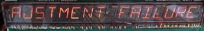
3n. When thing don't work: "Factory Setting" or "Adjustment Error" (Battery Problems)
Often when you buy a used system 11 game, upon power up, you'll get an error message stating, "Adjustment Error" (if the coin door is closed) or "Factory Setting" (if the coin door is open). This message indicates that the CPU RAM chip at location U25 on the CPU board has forgotten the game's bookkeeping and options settings.
"adjustment error" message.
If the coin is open, and the batteries are dead, you'll get a
"factory setting" message. You can also get either above
message
if the battery holder is bad, or the RAM chip at U25 has
failed.
- The difference between these two messages is simple; when the coin
door is closed (and the memory protect switch which is connected to
the coin door is pressed in), the CPU is electrically blocked from
accessing the RAM at U25. Therefore the game can only reset the
factory settings if the coin door is open. If the game ever comes up
with the "Adjustment Failure" message, the coin door must be opened to
get past this message.
Why Do I Get These Error Messages?
Most often, these
errors occurs because the three "AA" batteries on the CPU board have
died. These batteries should be replaced every year with good quality
alkaline batteries (batteries are cheap, battery damage is expensive).
The three batteries must keep at least +4 volts of power to the U25
RAM chip for it to remember. When power goes below +4 volts, memory
reset can occur (and you get the "Factory Setting" error message).
- The Battery Holder: a Weak Link.
If after replacing the batteries, you still get a "Factory Setting" error, suspect the battery holder. Use your DMM and check the battery voltage at the CPU board. With the game off, put your DMM on DC volts and put the black lead on ground (the grounding strap or on one of the screws holding the CPU board in place). Put the red lead on each of the CPU board's POSITIVE battery terminal SOLDER POINTS. Test each of the three batteries' positive leads individually. You should get about 1.5, 3.0, or 4.5 volts at each battery (note the batteries are additive and the first battery in the chain will give you 1.5 volts, and the last battery will give you 4.5 volts). If you don't these positive voltages, suspect damaged battery holder terminals. These corrode quite often if new batteries aren't installed religiously. Replace the battery holder and re-test to ensure proper repair.
- A Better Replacement Battery Holder.
The best battery holder to buy is the new black plastic battery holder used in WPC-S and later games. This is Williams part# A-15814. This design of battery holder is much better than the original system 11 design, and will fit perfectly on a system 11 CPU board.
Testing for Battery Voltage.
After testing the batteries
at the battery holder, test for voltage at the blocking diode D2
(1N4148), which is next to the left bottom side of the battery hold on
the CPU board. With the game off, put the black lead on the backbox
ground strap, and put the red lead on either side of the diode. You
should get around 4.2 to 4.8 volts. The banded diode of the diode
connects to the U25 RAM chip pin 24, and should be about .5 volts less
than the non-banded side of the diode. If you only get voltage on only
one side of the diode (the non-banded side, which connects directly to
the battery), the diode is bad and needs to be replaced.
Next check for voltage at the U25 RAM chip. With the game off, you should get about 4.3 volts DC at pin 24 of chip U25 (ground is pin 20 by the way). If you don't, the battery voltage is not getting to the U25 RAM chip. This will cause the game will boot up with the "Factory Setting" or "Adjustment error". Note pin 24 of the 24 pin RAM chip is in the same position as pin 1 of the chip, but on the opposite row of pins. Pin 1 is designated with an impressed "dot" right on the top of the chip. This chip is a 2k by 8 CMOS static 24 pin RAM chip. The part number will be 2016 or 6116-L or NTE2128. Early system 11 games specify this chip as a 5177, but this chip can be replaced with a 6116 instead.
You can still have problems even if you installed new batteries and all the voltages check out. If your game is still giving "Factory Setting" or "Adjustment error", you may have a bad CPU U25 RAM chip. But make sure you double check that battery holder. Even minor corrosion can cause this problem. The voltages may all check out, but the corrosion may be enough to limit CURRENT, and cause this problem.
- More "Blocking" Diode D2 Problems.
The three AA batteries are connected to the U25 RAM chip via a "blocking" diode. This 1N4148 switching diode at D2 is connected in series between the battery and the U25 RAM chip. It's job is to prevent +5 volts from going back to the batteries (it only allows power from the batteries, not to them). Sometimes this diode shorts out or goes open. If this diode shorts, the CPU board will try and charge the three AA batteries! This will cause the batteries to leak, and could damage your CPU board. If the diode goes open, the batteries will never power the U25 RAM chip, and the game will boot up with the "Factory Setting" or "Adjustment error". Check this diode with the game off and your DMM set to the "diode" setting. You should get between .4 and .6 volts in one direction, and a null reading in the other direction. You can also test the diode (with the game off) by setting your DMM to DC volts. Put the black lead on ground, and you should get 4.2 to 4.8 volts on either side of diode D2 (the banded side will be about .5 volts higher). If you only get voltage on one side, the diode is open and needs to be replaced.
Changing
Batteries.
If your game is working, and it's time to replace
the batteries, follow this procedure. But the way, you should change
the batteries in your game every year, or every two years at most (to
prevent any battery leakage problems):
If you install new batteries with the game turned on, the machine will not forget the old option settings or bookkeeping totals.
Clearing a "Factory Setting" or "Adjustment Error"
Message.
To clear these messages, you first need to fix the
problem (replace the batteries and/or battery holder, replace the U25
RAM, etc.). After this is done, turn the game on. Then press the
center red coin door button into the down position. Now press the
black button closest to the coin door. If you have an "adjustment
error", the game will beep and flash the "factory setting" message.
Once you have the "factory setting" message, press the black button closest to the coin door twice. Then move the center red button to the up position. Then press the black button closest to the coin door again (twice if you had an "adjustment error" message). The game should now go into attract mode.
New CPU Batteries Die very Quickly.
Just to the side of
the battery holder on the CPU board, there are two "blocking" diodes,
D1 and D2. These form a diode bridge, blocking the battery voltage
from the power supply, and vice-versa. Where these two diodes meet,
power goes to the U25 RAM. This way when the game is on, power for the
U25 RAM is drawn from the power supply. But when the game is off,
power for the U25 RAM is drawn from the batteries.
If either diode D1 or D2 is bad, it can let the batteries attempt to power all the +5 volts logic for the whole CPU board when the game is powered off. Or it can let the +5 volts from the power supply attempt to charge the batteries when the game is powered on. In either case, this will cause the batteries to die quickly.
If you have batteries that are dying very quickly, replace both diodes D1 (1N5817) and D2 (1N4148) on the CPU board.
3o. When thing don't work: Miscellaneous Oddities
Problem: In attract mode, the pop bumper coil on my F-14 behaves normally (did not fire or energize). Once a game was started or test mode entered, the coil would fire and stay energized. In attract mode, the coil could be fired by hitting the pop bumper skirt switch (this is NOT normal behaviour, and the others pop bumpers did not work this way)! Grounding the metal tab of the Q69 TIP122 transistor while the game was in attract mode energized the coil and released it (properly).
Answer: A close look at the 7402 chip at U50 (which is the controlling TTL for this coil) revealed that pins 5 and 6 where shorted together. This was caused by a solder splash from a previous repair. Removing this short fixed the problem!
I turn my system 11 game on, and the score displays will only
show 0's and X's in the middle of them.
Problem: the game
thinks you have "slammed" it.
Answer: there is a slam switch inside the coin door, just above the coin door lock. This switch should be normally open. If this switch is shorted or bent closed, you will have this problem. Often people will accidentally bend this switch when putting credits on the game (a good reason to have the game set on free play!). If the switch is not shorted closed, the switch matrix could also be damaged, as the slam switch is part of the switch matrix. See the Switch Matrix section of this guide for info on fixing that.
A system 11 game coil is always energized.
Problem: "I
have a system 11 game with solenoid problems. I have replaced the
TIP122 transistor, the associated pre-driver transistor, the 7408
chip, and even the 6821 PIA. But nothing keeps the solenoid from
staying energized."
Answer: some 50 volt coils are driven by a TIP36 transistor on the Auxiliary power driver board. If the TIP36 is shorted, the coil will stay energized (regardless of what you replaced further up the electronic river).
"When I turn my Fire! game on, the score displays would flash
quickly at a high brightness, and the speakers would be noisy, but the
game does nothing more."
Problem: the CPU board has a blanking
circuit problem. The job of the blanking circuit is to shut down the
score displays, solenoids and lamp circuits if there is a problem on
the CPU. This safety circuit also protects other circuits during
power-on if there is a problem.
Answer: there were two failed components, a 555 timer chip at U43 and a bad 2N4403 transistor at Q50.
To test the blanking circuit for proper operation, check U20 pin 2 or U43 pin 3 at power-on, using a logic probe. You should get an initial LO for a few seconds, followed by a continuous HI after the game has booted.
All score displays are out, game will start but flippers and ball eject do not work. While the game was being played (when it worked) the displays began acting strangely then the game died. Any further attempts to start a game resulted in above problems.
Answer: Examining the display board discovered a glob of flux on U11 (4050 hex buffer) shorting pins 14 and 15 together. Using the schematics and wiring diagrams was able to trace those pins back to the CPU board. The short killed U51 (PIA 6821) on the CPU board. Removed U51 (6821), added machine pin socket, and replaced it with a new 6821 PIA.
"No Sound on my Pinbot."
Problem: The sound on the Pinbot
just suddenly died. The amplifier section seems to work, because when
the volume control is turned, you can hear the scratching sound coming
from the speakers. Also when the sound test button is pressed on the
CPU board, you can faintly hear the sounds.
Answer: No -12 volts DC, which is used for the sound. In this case it ended up being the bridge rectifier that converted the 12 volts AC to DC voltage that had failed.
When the flipper button is pressed, the game resets. When the
ball hits the slingshot, the game tilts.
Problem: This is a
switch matrix problem. The low voltage (high score) switch on the
flippers and the slingshot scoring switch are triggering other
switches in the switch matrix.
Answer: First I would suggest looking for a bad, missing or mis-wired switch diode. But in reality this was not the problem. A switch matrix column transistor (2N3904) was bad, as was the switch matrix column resistor network SR15.
The CPU software for Road Kings on the Williams web site does
not seem to work.
Answer: Indeed the EPROM software for Road Kings on the Williams web site is bad. For working software, click here for working EPROM files.
On My F-14, I need a new rubber belt to drive the rotating
beacon lights. Where can I get this?
Answer: This rubber drive belt is available from any local John Deere tractor store! Just ask for part number H85996, cost is about $2.00.